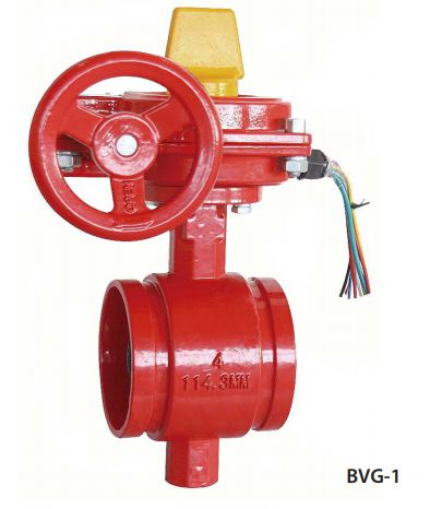
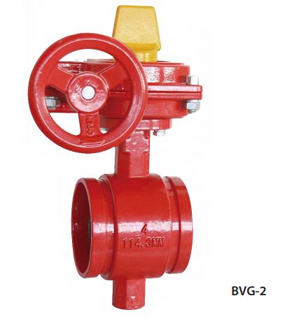
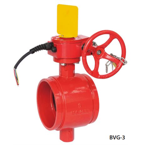
Butterfly Valves (Grooved) - UL/FM, VdS & French Market
BVG-1, BVG-2 & BVG-3
Technical Features
-
Models :
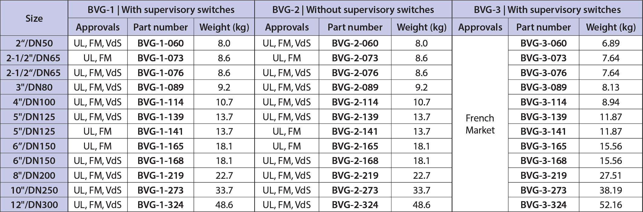
BVG-1:With switches
BVG-2:With switches
BVG-3:With switches - French market -
Sizes (Nominal):
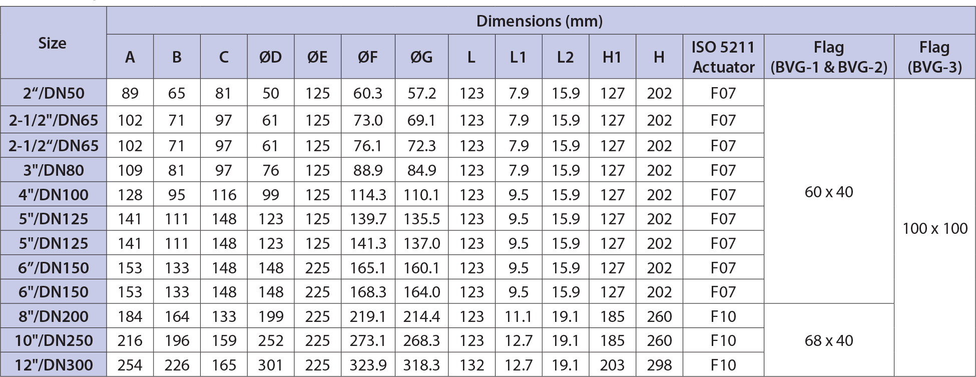
2”/DN50, 2-1/2” /DN65, 3”/DN80, 4”/DN100, 5”/DN125, 6”/DN150, 8”/DN200, 10”/DN250 & 12”/DN300
-
Approvals :
CE, UL, FM & VdS
-
Pressure data:
Working pressure: - 21 bar (300 psi) - UL/FM & French market - 16 bar (232 psi) - VdS
Test pressure:
- Model BVG-1 & BVG-2: Leak & Shell, 1.5x working pressure
- Model BVG-3: Leak 1.1x, Shell 1.5x working pressure -
Working temperature:
0°C to 80°C
-
Finish:
Epoxy coated ductile iron
-
Connections:
Grooved joint dimensions, in accordance with: ANSI/AWWA C606 or ISO 6182
-
Operation:
Gear operated
-
Supervisory switches:
- Model BVG-1 and BVG-3 gearboxes are fitted with one internal supervisory position switch and one internal auxiliary switch.
- Model BVG-3 switch cables are 1 m long.
- Model BVG-2 comes without supervisory switches - Notes:
- The valves are suitable for use outdoors. Some
degradation of the painted/coated surfaces may occur
(including rusting) which will not affect the
performance of the valve. The UL listing specifically
ensures the switch operation is not affected by
outdoor conditions, providing the proper installation
instructions are followed.
- Model BVG-3 comes with a padlock and chain.
* CE, UL, FM & VdS (BVG-1 & BVG-2), CE & French market (BVG-3)
BVG-1, BVG-2 & BVG-3
Dimensions
BVG-1, BVG-2 & BVG-3
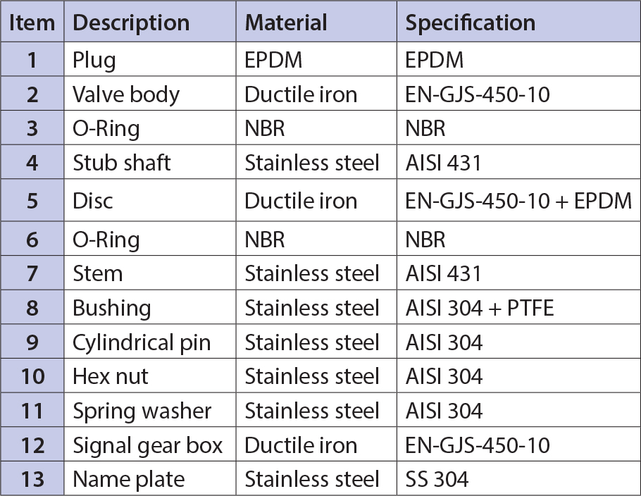
Materials
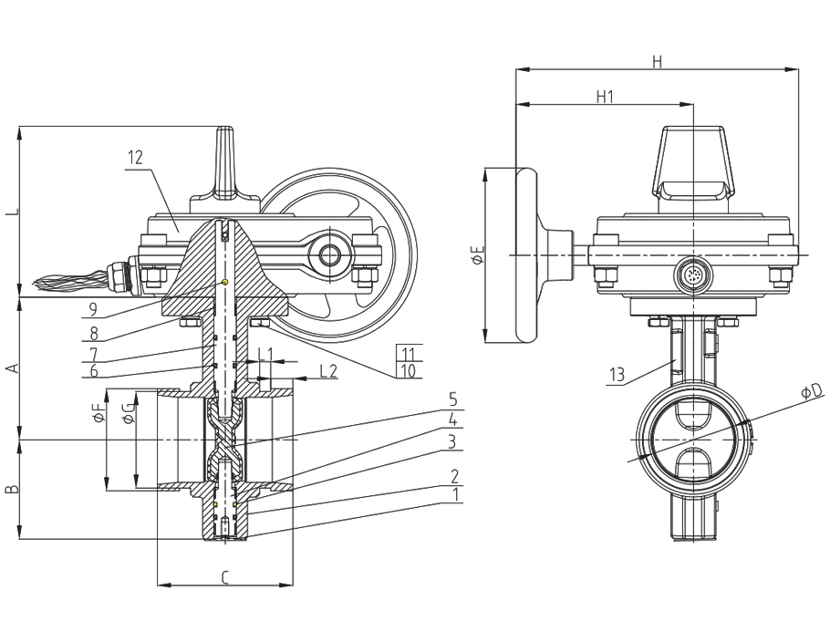
BVG-1, BVG-2 & BVG-3
Part Numbers and Technical Data
Design requirements
The butterfly valve should be connected to the piping system with approved couplings. Flow may be from either direction through the valve, and the valve may be positioned in any direction. The gearbox has been designed with a slow close handwheel operator that effectively minimizes water hammer during the opening or closing of valve during flow conditions. These valves feature minimum flow restriction and pressure loss when in the fully open position.
Installation
When the valves are received from Viking they should be handled carefully to avoid breakage and damage to the seating area. Before installation of the valve:
- Check the valve pressure rating is compatible with service conditions.
- Clean the piping, and connecting couplings.
- Position the valve centrally between mating pipes
- Lubricate the coupling gaskets and slide them into position. Assemble the couplings according to their instructions.
- The valve should be installed in an almost closed position.
- Interference between the butterfly valve disc and the mating pipes should be avoided under all circumstances. Before fully tightening the coupling bolts, carefully open the valve to the open position and check for any disc interference.
- To prevent distortion, properly support the piping adjacent to the inlet and outlet of the valve. Avoid damage and do not use the valve to force the piping into position.
- The valve should never be forced to seat by applying excessive torque to the gearbox or through the use of a wrench. This may distort the valve components or score the sealing surface. The use of excessive force to open or close the valve violates all warranties whether express or implied.
- Conduit and electrical connections to the supervisory/ auxiliary switches must be in accordance with the requirements of the Authority Having Jurisdiction.
Care and maintenance
Inspect and verify proper operation on an annual basis or according to the requirements of the Authority Having Jurisdiction. Check for leakage at the valve pipe connection and body-to-operator connection. Installation, inspection and maintenance should be performed by a qualified person certified by the Authority Having Jurisdiction. If the valve closes hard, check to make sure that there is no debris lodged in the waterway around the seating area. Backing off the handwheel and closing the valve again can often correct this condition.
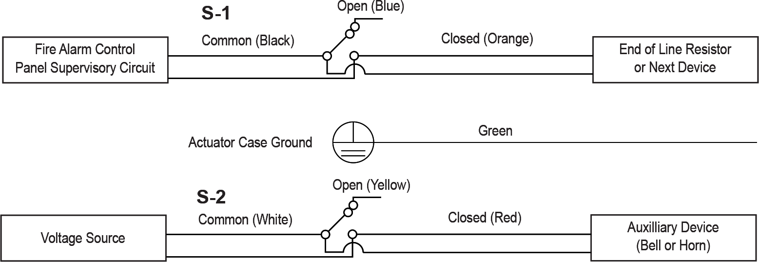
Wiring instructions (BVG-1 & BVG-3)
The BVG-1 and BVG-3 butterfly valves come complete with one internal supervisory position switch and one internal auxiliary switch. The supervisory/auxiliary switches operate by a cam connected to the valve stem and are designed to notify in the case of valve closure. Please refer to the relevant installation standard and Authority Having Jurisdiction. The switches will change position and close within two (2) full turns of the hand wheel from the fully open position.