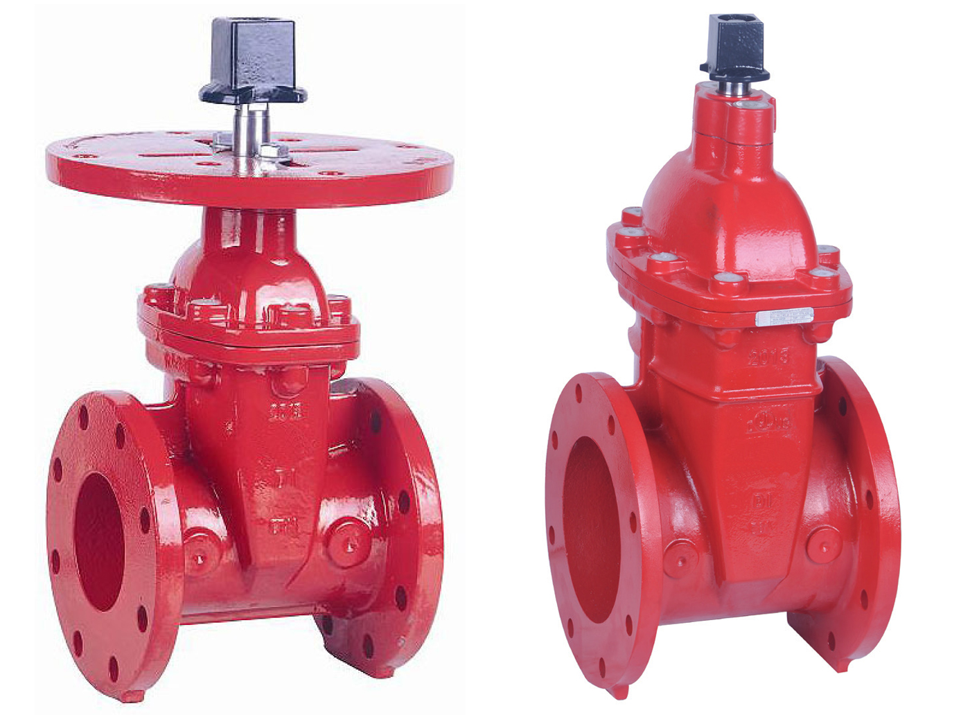
Post Indicator Valve - Flanged
PIF
Technical Features
- Sizes available (Nominal) : 2”/DN50, 2-1/2”/DN65, 3”/DN80, 4”/DN100, 5”/DN125, 6”/DN150, 8”/DN200, 10”/DN250, 12”/DN300, 14”/DN350, 16”/DN400, 18”/DN450, 20”/DN500 & 24”/DN600
- Working pressure : 4”-12”: 21 bar (300 psi) 2”, 14” & 16”: 17 bar (250 psi)
- Seat type : Resilient wedge
- Finish : Fusion bonded epoxy coated internal & external
- Connections : Flange diameter and thickness according to ANSI B16.1 Class 125, EN1092-2 PN10 or EN1092-2 PN16
- Specifications : Design and dimensions conform to AWWA C515
- Operation : For use with IPV (≥ 4”) or IPW indicator posts
- Remark : No post flange supplied with 2”-3” and 14” and above, and size 2” is FM approved only and size 5” is UL listed only
* Image depicts 4”-24” sizes, 2”-3” and 14” and above are supplied without a post plate and should be used with a T-Key
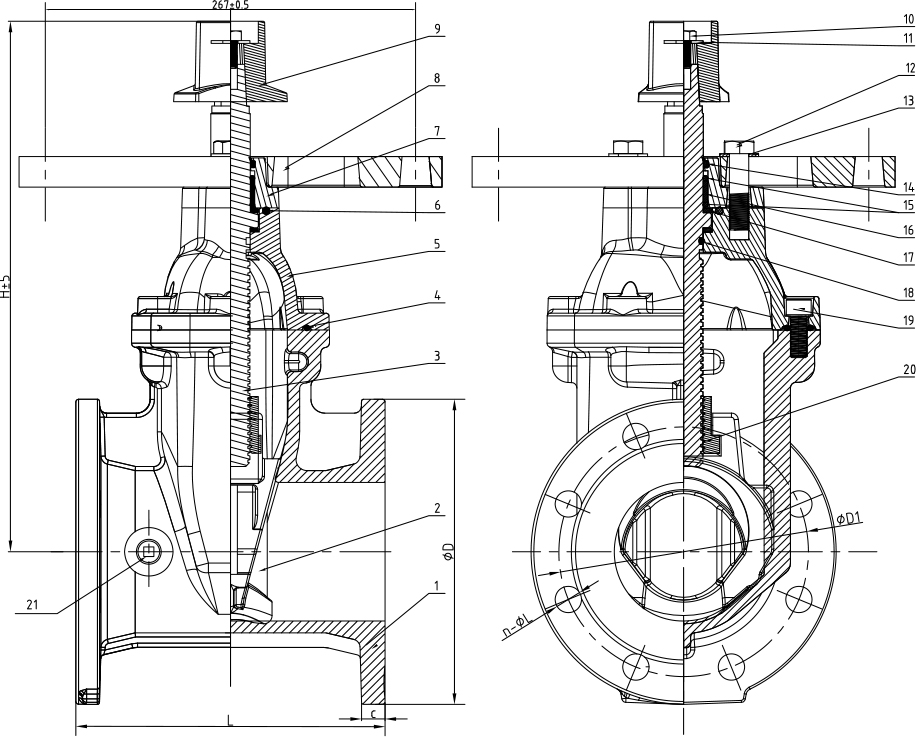
Post Indicator Valve - Flanged - PIF
Physical Data
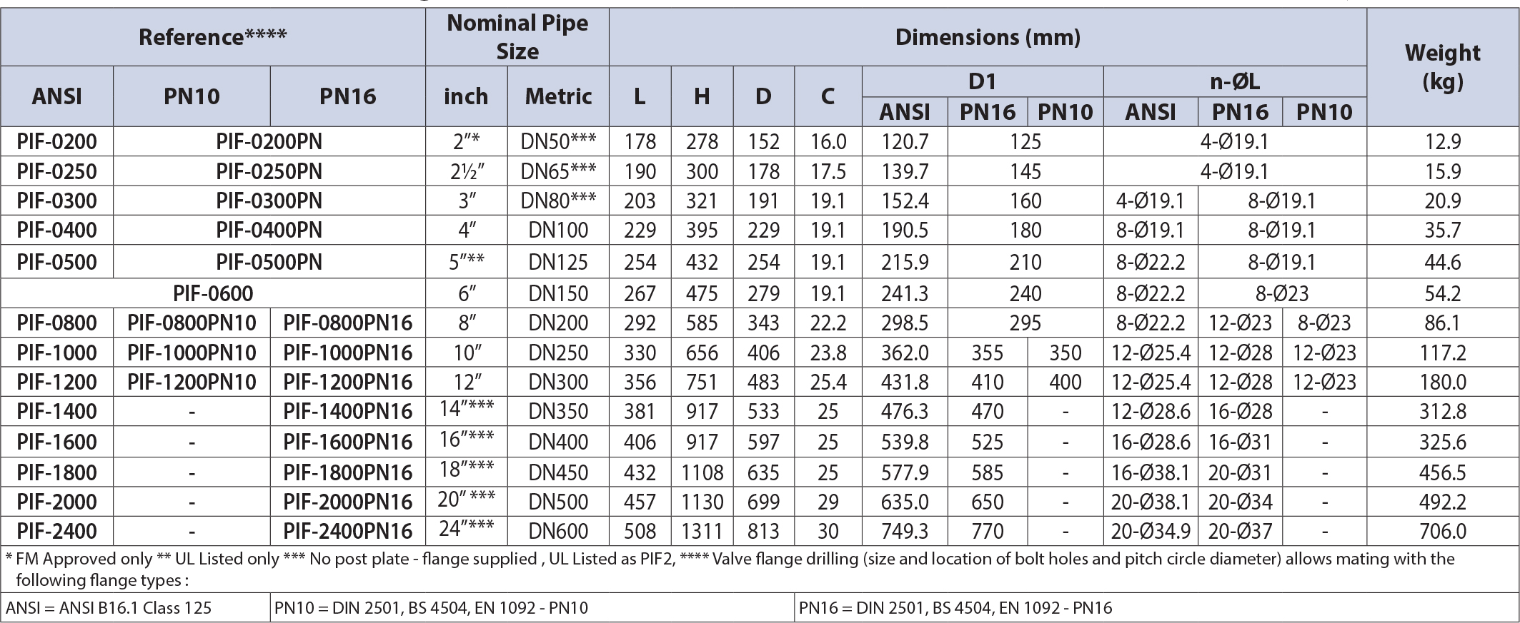
Post Indicator Valve - Flanged - PIF
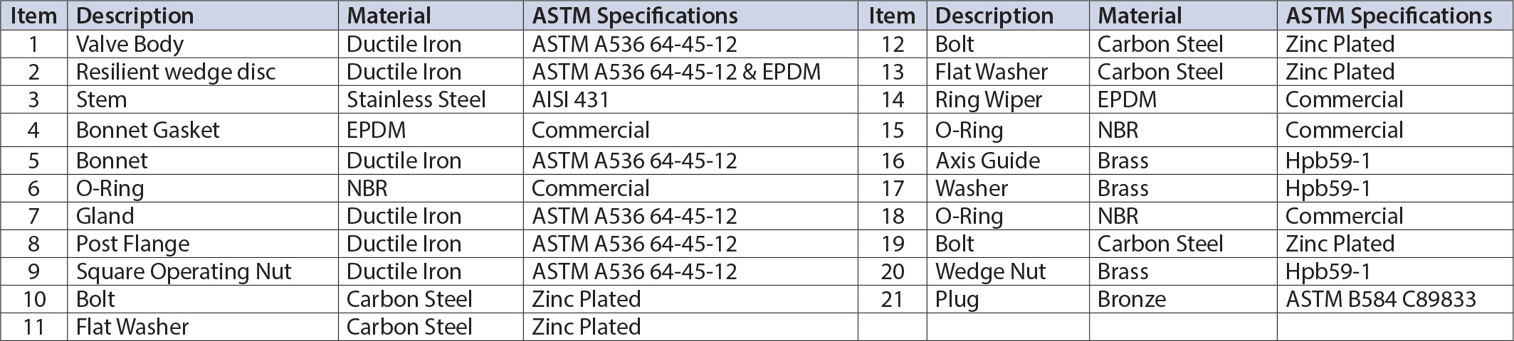
Materials List
Installation
- Piping systems and valves should be thoroughly cleaned and free from ingress of foreign materials.
- Visually inspect the valve seating and ports for cleanliness immediately prior to installation.
- All valves should be independently supported against movement and stress from the connected piping system.
- Ensure that the valve pressure rating is compatible with service conditions.
- Operate the valve at least once from the open to closed position.
- Gate valves are not suitable for throttling applications.
- Gate valves should be installed in the vertical position on horizontal pipework and in the horizontal position on vertical pipework.
- See indicator post datashet for further installation instructions.
Inspection and Maintenance
- Valves should be inspected periodically and should be cycled to prevent buildup of foreign materials in the piping system and valve body.
Operation
Gate valves are manually operated multi-turn valves and are opened by a handwheel or other operating device, generally in a counter clockwise direction and then closed clockwise