DELUGE VALVE MODEL F-1 STRAIGHT THROUGH STYLE
1-1/2” (DN40) & 2” (DN50)
DESCRIPTION
The Viking Model F-1 Deluge Valve is a quick opening, differential diaphragm, flood valve with one moving mechanism. The Deluge Valve is used to control water flow in Deluge and Preaction sprinkler systems. The valve is held closed by system water pressure trapped in the priming chamber; keeping the outlet chamber and system piping dry. In fire conditions, when the releasing system operates, pressure is released from the priming chamber. The Deluge Valve clapper opens to allow water to flow into the system piping.
Features
- Field replaceable Diaphragm and Seat Rubbers
- Designed for installation in horizontal or vertical position
- Designed to be reset without opening the valve
- Compatible with Hydraulic, Pneumatic and Electric Release Systems
LISTINGS AND APPROVALS:
cULus Listed: Guide No. VLFT & VLJH
FM Approved: Deluge Sprinkler Systems, Preaction Sprinkler Systems, Refrigerated Area Sprinkler Systems
NYC Department of Buildings: MEA 89-92-E Vol. XXXI
American Bureau of Shipping (ABS): Certificate No. 15-HS1332725-PDA
CE: Pressure Equipment Directive 97/23/EC
TECHNICAL DATA
Specifications:
Maximum working water pressure: 250 PSI (17.4 bar)
Style: Straight through
Connections: Refer to Table 1
Factory tested to 500 psi (34.5 bar)
Valve differential: over 2:1 (priming chamber to inlet chamber)
Priming chamber supply restriction (required): 1/16” (1.6 mm)
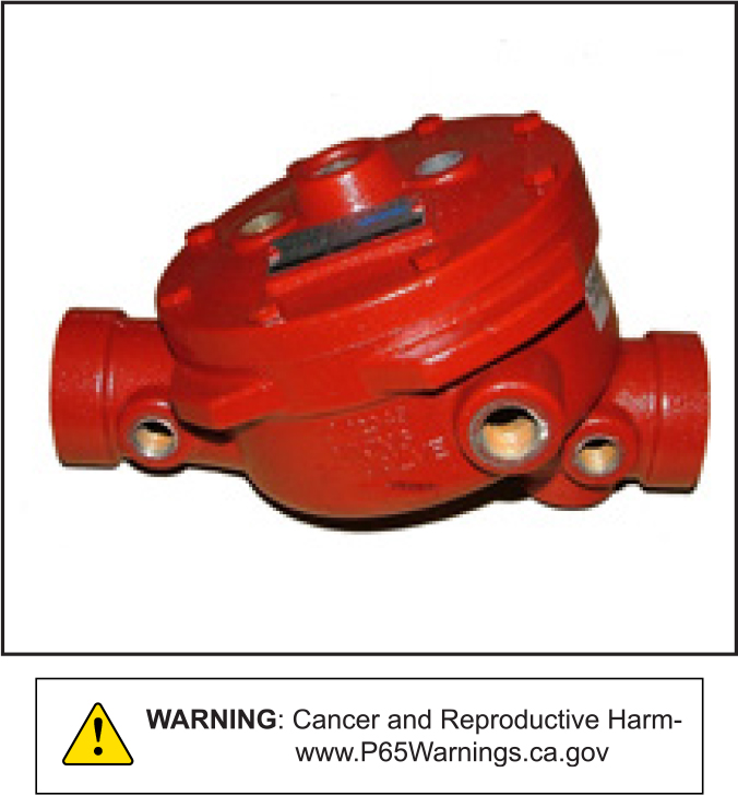
Color: Red
Friction loss: Refer to Table 1
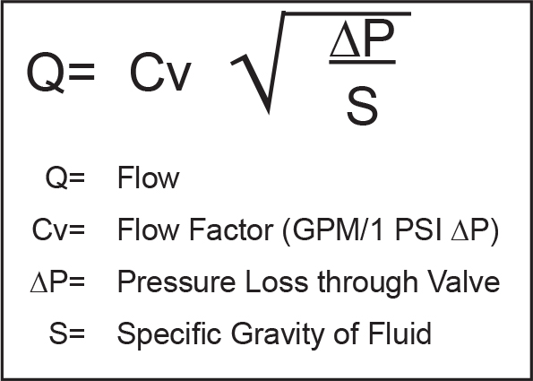
Cv Factor: Refer to Table 1
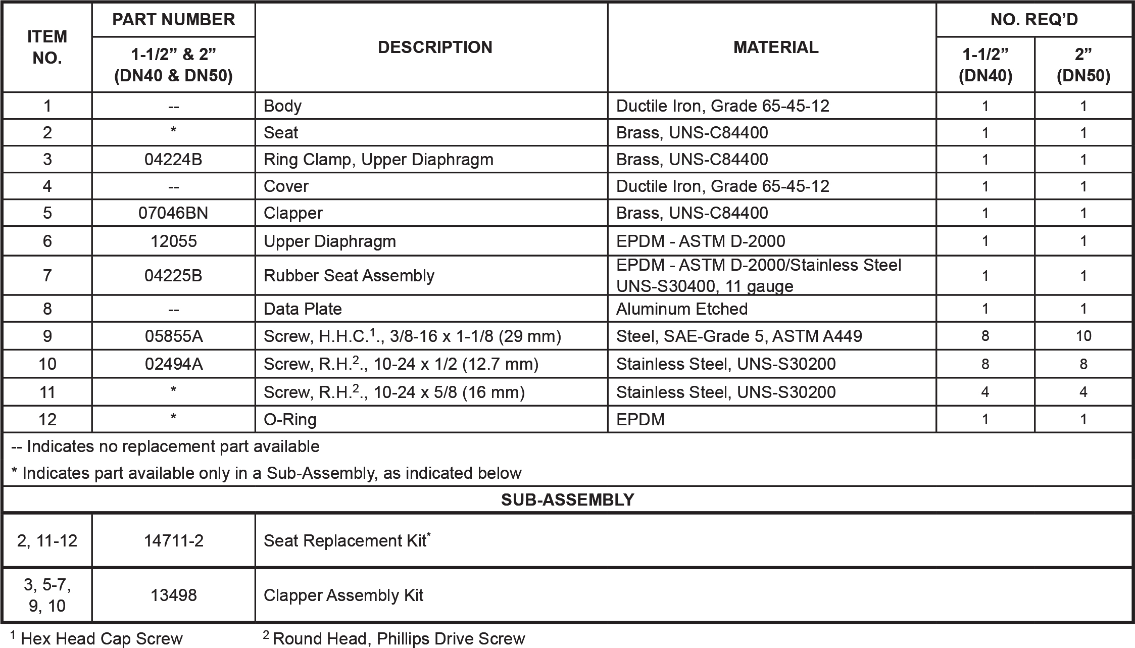
Material Standards:
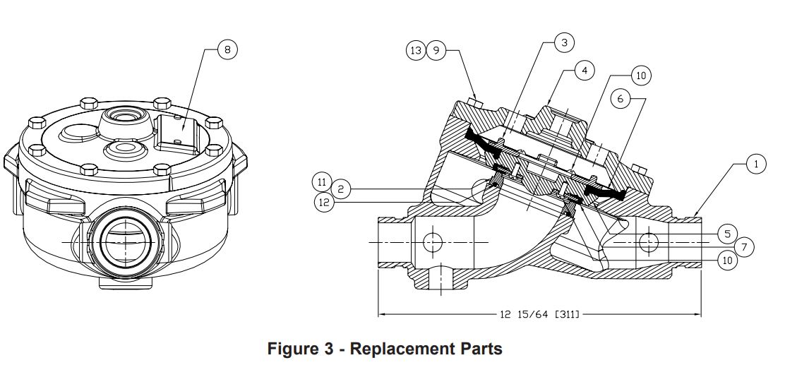
Refer to Figure 3
Ordering Information:
Part Numbers: Refer to Table 1
Shipping Weight: Refer to Table 1
Available Since 2004
Accessories:
Refer to Current Viking Price List for Part Numbers.
- A STANDARD TRIM package is available. The trim package includes the VALVE ACCESSORY PACKAGE and the fittings and nipples shown on the Viking Deluge Valve Conventional Trim Chart Trim Chart for the valve used. Trim Charts are provided in trim packages and the Viking website. For optional factory assembled “modular” trim packages, refer to the Viking list price schedule or contact the manufacturer.
- Deluge VALVE ACCESSORY PACKAGE includes required trim components. This package is needed when Viking Trim Packages are not used.
- Additional accessories are available and may be required for system operation or supervision. Refer to the system description and technical data for complete operating trim requirements for the system used.
INSTALLATION
A. General Instruction
- Viking Deluge Valves may be installed in the horizontal or vertical position.
- The valve must be installed in an area not subject to freezing temperatures or physical damage.
- The valve must be trimmed according to current Viking Trim Charts and appropriate instructions for the system used. Trim Charts are printed in the Viking website, and are provided with trim packages.
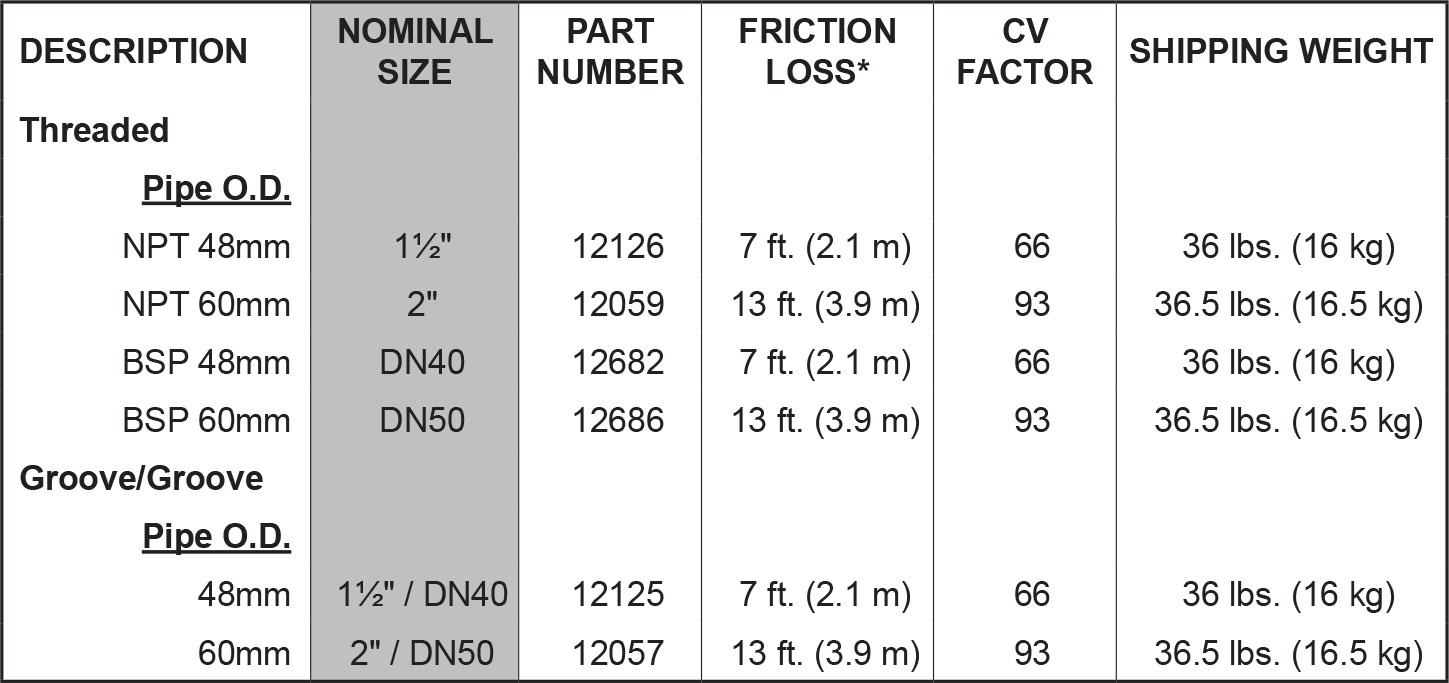
* Expressed in equivalent length of pipe based on Hazen & Williams Formula. C-120
Table 1 - Valve Part Numbers and Specificationsa. Remove all plastic protectors from the openings of the Deluge Valve
b. Apply a small amount of pipe joint compound or tape to the external threads of all pipe connections required. Take care not to allow any compound, tape, or other foreign matter inside any of the nipples or openings of the valve or trim components.
c. Verify that all system components are rated for the water working pressure of the system
4. Hydrostatic Test: The Model F-1 Deluge Valve is manufactured and listed for use at a maximum Water Working Pressure of 250 PSI (17.2 bar). The valve is factory tested at 500 PSI (34.5 bar). Model F-1 Deluge Valves may be hydrostatically tested at 300 PSI (20.7 bar) and/or 50 PSI (3.5 bar) above the normal Water Working Pressure, for limited periods of time (two hours), for the purpose of acceptance by the Authority Having Jurisdiction. If air testing is required, do not exceed 60 PSI (4.2 bar) air pressure.
NOTE: NEVER CONDUCT THE HYDROSTATIC TEST AGAINST THE PRESSURE OPERATED RELIEF VALVE. (PORV) TEMPORARILY REMOVE THE PORV FROM THE TRIM AND PLUG TRIM OPENINGS WHILE CONDUCTING THE HYDROSTATIC TEST.
TRIM NOTE: DISCHARGE PIPING FROM THE AUXILIARY DRAIN VALVE, THE FLOW TEST VALVE, AND ALL SYSTEM DRAINS SHOULD BE KEPT SEPARATE. DO NOT CONNECT THE OUTLET OF THE DRIP CHECK TO ANY OTHER DRAIN.
5. The priming line must be connected upstream of the system water supply main control valve or to a constant source of water at a pressure equal to the system water supply.
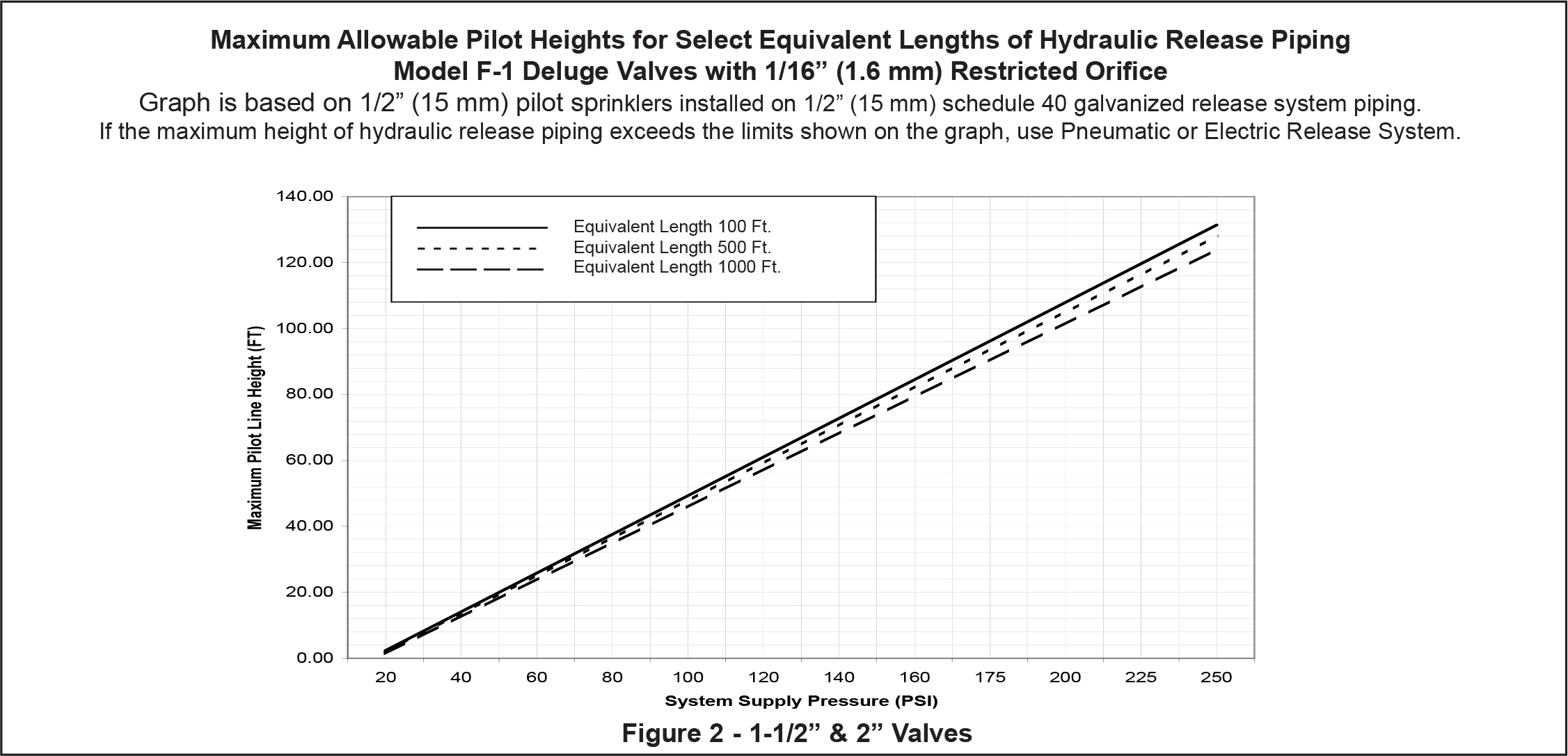
6. After the Deluge Valve is set, operation of the Deluge Valve requires the release of priming water from the priming chamber. This may be by automatic or manual operation of the release system. Viking Deluge Valves are compatible with hydraulic, pneumatic, and electric release systems.
a. Hydraulic Release Systems: See Figure 2 for the maximum allowable elevation of hydraulic release piping above the Deluge Valve. If the maximum height of hydraulic release piping exceeds the limit shown in Figure 2, use a Pneumatic or Electric Release System.
b. Pneumatic Release Systems: A Viking Pneumatic Actuator is required between the release system connection provided on deluge valve trim and pneumatic release Piping.
c. Electric Release: Solenoid Valves, System Control Panels, and Electrical Detectors must be compatible. Consult appropriate listing and/or approval guides.
NOTE: FOR OPERATION AT WATER PRESSURES IN EXCESS OF 175 PSI, A 250-PSI RATED SOLENOID VALVE MUST BE USED.REFER TO APPROPRIATE VIKING TECHNICAL DATAPAGE FOR TYPE OF SYSTEM USED.
CAUTION
Operation of Viking Deluge Valves by pressurizing the priming chamber with air pressure or any other pressurized gas is not recommended or approved.
B. Placing the Valve in Service
For Deluge Valves equipped with Conventional Deluge Valve Trim, follow steps 1 through 10 (and 11 & 12 if applicable) below.
1. Verify:
a. The system Main Water Supply Control Valve (D.1) is closed and the Deluge Valve is trimmed according to current VikingTrim Charts and schematic drawings for the system used.
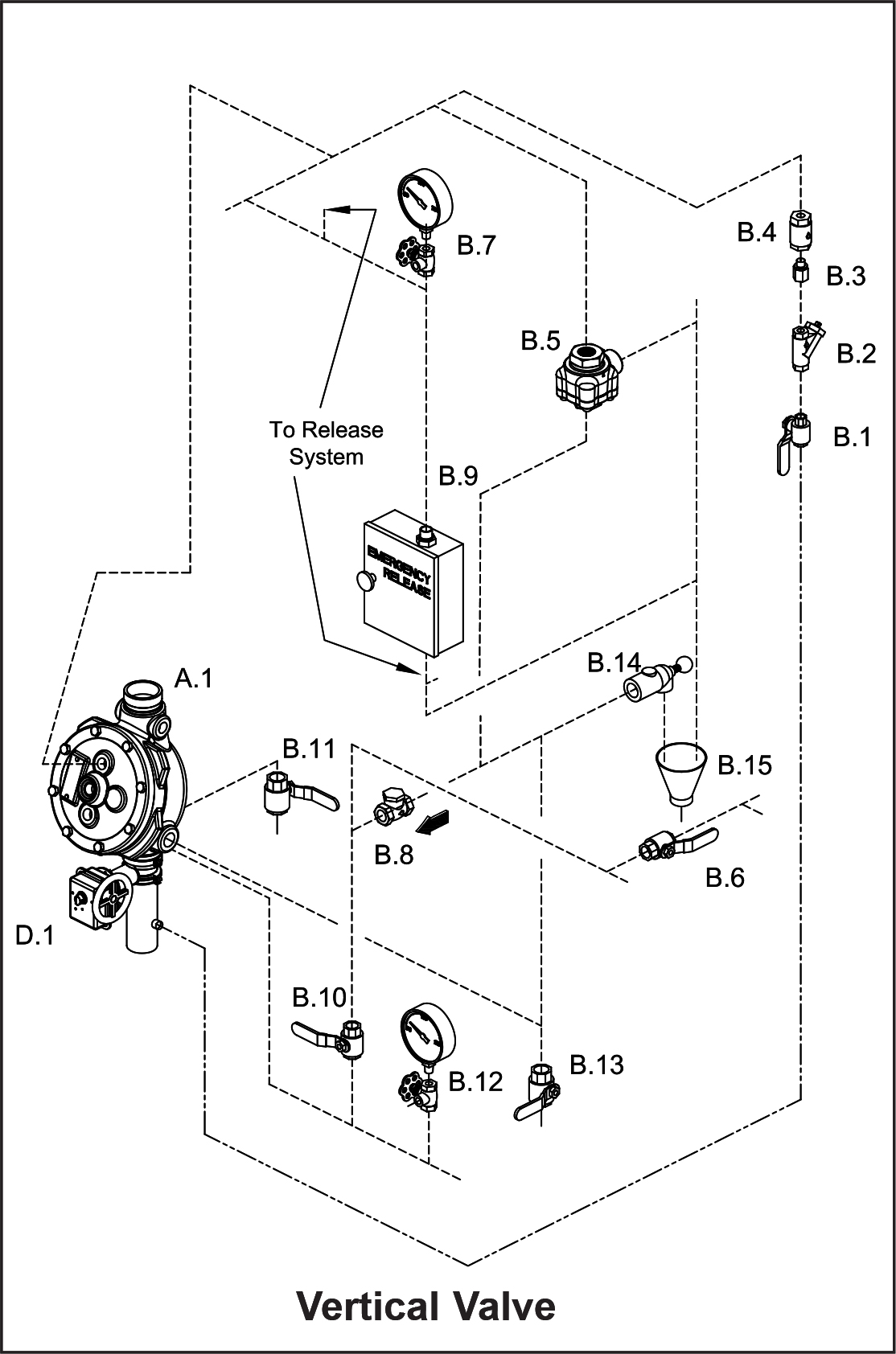
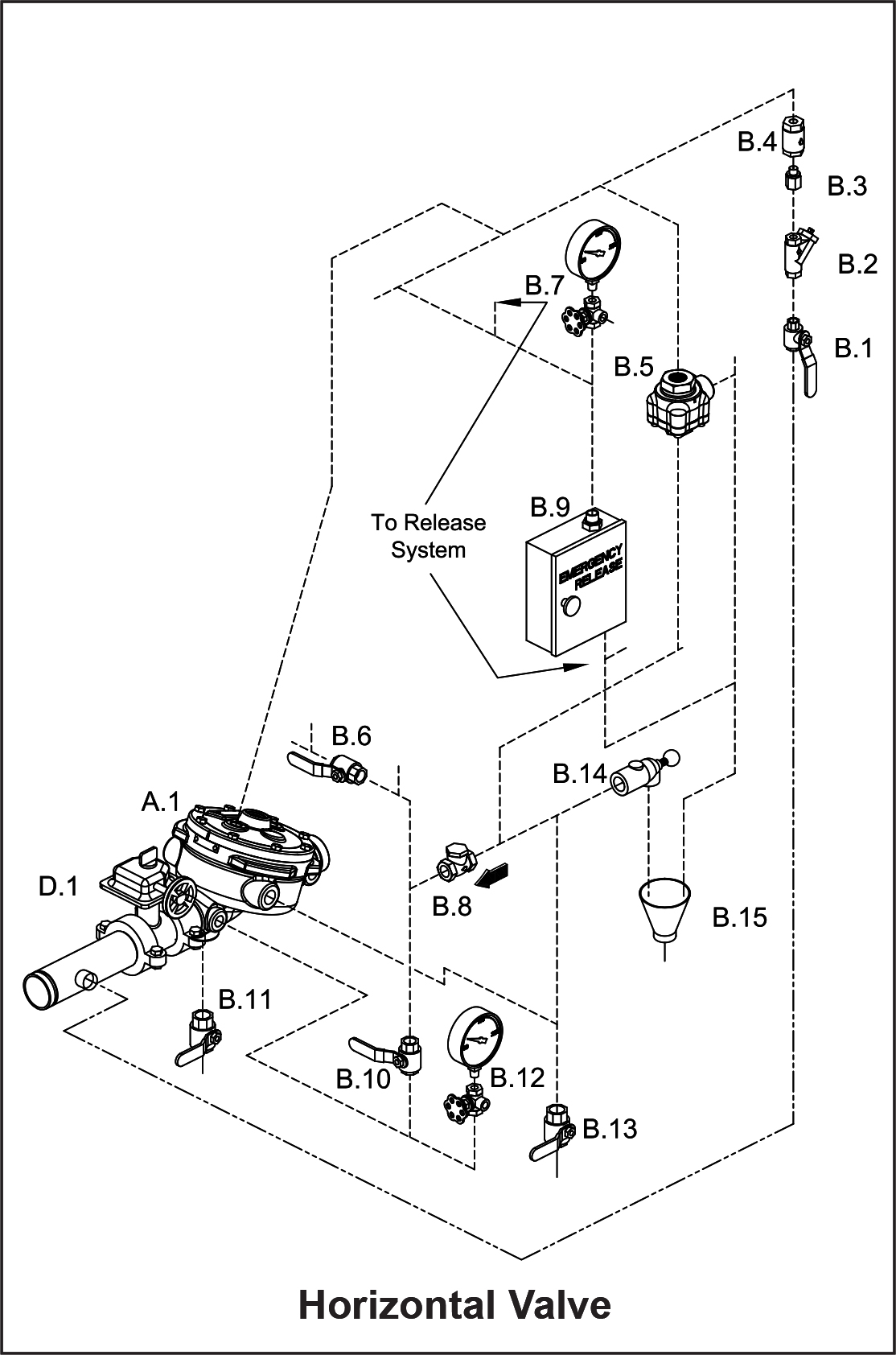

Figure 1 - Conventional Trim Components
A.1 Deluge Valve
B.1 Priming Valve (Normally Open)
B.2 Strainer
B.3 1/16" Restricted Orifice
B.4 Spring Loaded Check Valve
B.5 Pressure Operated Relief Valve (PORV)
B.6 Alarm Shut Off Valve (Normally Open)
B.7 Priming Pressure Water Gauge and Valve
B.8 Drain Check Valve
B.9 Emergency Release
B.10 Alarm Test Valve (Normally Closed)
B.11 Flow Test Valve (Normally Closed)
B.12 Water Supply Pressure Water Gauge and Valve
B.13 Auxiliary Drain Valve (Normally Closed)
B.14 Drip Check Valve
B.15 Drain Cup
D.1 Water Supply Control Valve
b. The system has been properly drained.
c. Auxiliary Drain (B.13) is open.
d. The Emergency Release (B.9) is closed.
e. The system water supply piping is pressurized up to the closed Main Water Supply Control Valve (D.1) and the priming line
is pressurized up to the closed Priming Valve (B.1).
2. For Systems equipped with:
a. Hydraulic Release Systems:
i. Verify that all releasing devices are set and that any Inspector’s Test Valve and/or auxiliary drain valves are closed.
ii. Open Priming Valve (B.1). Allow the hydraulic release system to fill. When priming pressure gauge (B.7) indicates that
the release piping and priming chamber pressure is equal to system supply pressure, proceed to step 3.
b. Pneumatic Release Systems:
i. Set the release system.
ii. Open Priming Valve (B.1). Proceed to step 3
c. Electric Release Systems:
i. Open Priming Valve (B.1).
ii. Set the electric release system. Proceed to step 3.
3. Open Flow Test Valve (B.11).
4. Partially open Main Water Supply Control Valve (D.1).
5. When full flow develops from the Flow Test Valve (B.11), close the Flow Test Valve. Verify that there is no flow from the open Auxiliary Drain (B.13).
6. Close Auxiliary Drain (B.13).
7. Fully open and secure the Main Water Supply Control Valve (D.1).
8. Verify that the Alarm Shut-off Valve (B.6) is open and that all other valves are in their normal operating position. (Refer to Figure 1, page 214b and/or Trim Charts and System Data for the system used.)
9. Depress the plunger of Drip Check (B.14). No water should flow from the Drip Check when the plunger is pushed.
10. Check for, and repair all leaks.
11. On new installations, those systems that have been placed out of service, or where new equipment has been installed, trip test the system to verify that all equipment functions properly. Refer to Annual Trip Tests, paragraph 6.II.C.
12. After completing a trip test, perform SEMI-ANNUAL maintenance.
CAUTION
Performing a trip test results in operation of the Deluge Valve. Water will flow into the sprinkler piping. Take necessary precautions to prevent damage.
C. Valve Removed From Service
NOTE: WHEN A VALVE HAS BEEN REMOVED FROM SERVICE AND IS SUBJECT TO FREEZING OR WILL BE OUT OF SERVICE FOR
AN EXTENDED PERIOD OF TIME, ALL WATER MUST BE REMOVED FROM THE PRIMING CHAMBER, TRIM PIPING, WATER SUPPLY
PIPING AND OTHER TRAPPED AREAS.
OPERATION
(Refer to Figure 3)The Viking Model F-1 Deluge Valve has an inlet chamber, an outlet chamber and a priming chamber. The inlet chamber and outlet chamber are separated from the priming chamber by the clapper (5) and diaphragm (6).
In the set condition:
System pressure is supplied to the priming chamber through a restricted priming line (trim) equipped with a check valve. System water supply pressure trapped in the priming chamber holds the clapper (5) on seat (2) due to area differential design. Clapper (5) separates the inlet chamber from the outlet chamber, keeping the outlet chamber and system piping dry.
In fire conditions:
When the release system operates, pressure is released from the priming chamber faster than it is supplied through the restricted priming line. Water supply pressure in the inlet chamber forces the clapper (5) off from seat (2), allowing water to flow through the outlet and into the system and alarm devices.
Deluge Valves equipped with Conventional Trim:
When the deluge valve operates, the air side of the PORV looses pressure, causing the PORV to operate. When the PORV operates, it continually vents the priming chamber to prevent the deluge valve from resetting even if the open releasing devices close. The deluge valve can only be reset after the system is taken out of service, and the outlet chamber of the deluge valve and associated trim piping is depressurized and drained.
INSPECTIONS, TESTS AND MAINTENANCE
NOTICE
The owner is responsible for maintaining the fire protection system and devices in proper operating condition. The Deluge Valve must be kept from freezing conditions and physical damage that could impair its operation.
WARNING
Any system maintenance which involves placing a control valve or detection system out of service may eliminate the Fire Protection capabilities of that system. Prior to proceeding, notify all Authorities Having Jurisdiction. Consideration should be given to employment of a Fire Patrol in the affected areas.
I. Inspection
It is imperative that the system be inspected and tested on a regular basis. The frequency of the inspections may vary due to contaminated water supplies, corrosive water supplies or corrosive atmospheres. Also, the alarm devices, detection systems or other connected trim may require a more frequent schedule. For minimum maintenance and inspection requirements, refer to NFPA 25. In addition, the Authority Having Jurisdiction may have additional maintenance, testing, and inspection requirements which must be followed. The following recommendations are minimum requirements.
A. Weekly -
Weekly visual inspection of the Viking Deluge Valve is recommended.1. Verify that the Main Water Supply Control Valve (D.1) is open and that all other valves are in their normal operating position and
appropriately secured. (refer to Figure 1 and/or Trim Charts and System Data for the system used)
2. Check for signs of mechanical damage, leakage, and/or corrosive activity. If detected, perform maintenance as required. If necessary, replace the device.
3. Verify that the valve and trim are adequately heated and protected from freezing and physical damage.
** For normal operating position, refer to Figure 1 and/or Trim Charts and System Data for the system used.
II. Tests
A. Quarterly Water Flow Alarm Test
Quarterly testing of water flow alarms and performance of a Main Drain Test is recommended and may be required by the Authority
Having Jurisdiction.
1. Notify the Authority Having Jurisdiction and those in the area affected by the test.
2. To test the local electric alarm (if provided) and/or mechanical water motor alarm (if provided), OPEN the alarm test valve (B.10)
in the Deluge Valve trim.
a. Electric alarm pressure switches (if provided) should activate.
b. Electric local alarms should be audible.
c. The local water motor gong should be audible.
d. If equipped with remote station alarm signaling devices, verify that alarm signals were received.
3. When testing is complete, CLOSE the Alarm Test Valve (B.10).
4. Verify:
a. All local alarms stop sounding and alarm panels (if provided) reset.
b. All remote station alarms reset.
c. Supply piping to water motor alarm properly drains.
5. Verify that the Alarm Shut-off Valve (B.6) is OPEN, and the Alarm Test Valve (B.10) is CLOSED.
6. Verify that the outlet chamber is free of water. No water should flow from the Drip Check (B.14) when the plunger is pushed.
7. Notify the Authority Having Jurisdiction and those in the affected area that testing is complete.
B: Quarterly Main Drain Test
1. Notify the Authority Having Jurisdiction and those in the area affected by the test.
2. Record pressure reading from the water supply pressure gauge (B.12).
3. Verify that the outlet chamber of the Deluge Valve is free of water. No water should flow from the drip check (B.14) when the
plunger is pushed.
4. Fully OPEN the Flow Test Valve (B.11).
5. When a full flow is developed from the Flow Test Valve (B.11), record the residual pressure from the water supply pressure gauge
(B.12).
6. When the test is complete, SLOWLY CLOSE the Flow Test Valve (B.11).
7. Compare test results with previous flow information. If deterioration of the water supply is detected, take appropriate steps to
restore adequate water supply.
8. Verify:
a. Normal water supply pressure has been restored to the inlet chamber, the priming chamber, and the release system. The
pressure on the priming chamber water pressure gauge should equal the system water supply pressure.
b. All alarm devices and valves are secured in normal operating position (refer to Figure 1 and/or Trim Charts and System Data
for the system used).
9. Notify the Authority Having Jurisdiction that the test is complete. Record and/or provide notification of test results as required by
the Authority Having Jurisdiction.
C. Annual Trip Tests
CAUTION
Performing this test results in operation of the Deluge Valve. Water will flow into the sprinkler piping and from any open sprinklers and/or nozzles. Take necessary precautions to prevent damage.
1. Notify the Authority Having Jurisdiction and those in the area affected by the test.
2. Fully open the Flow Test Valve (B.11) to flush away any accumulation of foreign material.
3. Close the Flow Test Valve (B.11).
4. Trip the system by operating the release system. Allow a full flow to pass through the Deluge Valve. Water flow alarms should
operate.
5. When test is complete:
a. Close the Main Water Supply Control Valve (D.1).
b. Close the Priming Valve (B.1).
c. Open the Auxiliary Drain Valve (B.13).
d. Open all system main drains and auxiliary drains. Allow the system to drain completely.
6. Perform semi-annual maintenance. Refer to paragraph 6.III.B Semi-Annual Maintenance.
7. Place the system in service. Refer to Item 4.B.
8. Notify the Authority Having Jurisdiction that the test is complete. Record and/or provide notification of test results as required by
the Authority Having Jurisdiction.
III. Maintenance
NOTICE
Where difficulty in performance is experienced, the valve manufacturer or his authorized representative shall be contacted if any field adjustment is to be made.
A. After Each Operation:
1. Sprinkler systems that have been subjected to a fire must be returned to service as soon as possible. The entire system must be
inspected for damage, and repaired or replaced as necessary.
2. Deluge Valves and trim that have been subjected to brackish water, salt water, foam, foam/water solution, or any other corrosive
water supply, should be flushed with good quality fresh water before being returned to service.
3. Perform SEMI-ANNUAL maintenance after every operation.
B. Semi-Annual Maintenance:
1. Remove the system from service. (Refer to Deluge or Preaction System Data that describes systems with the release system
used for additional information.)
a. Close the Main Water Supply Control Valve (D.1) and Priming Valve (B.1).
b. Open the Auxiliary Drain Valve (B.13).
c. Relieve pressure in the priming chamber by opening the Emergency Release Valve (B.9).
2. Inspect all trim for signs of corrosion and/or blockage. Clean and/or replace as required.
3. Clean and/or replace all strainer screens (including B.2).
4. Refer to Item 4.B.
C. Every Fifth Year
1. Internal inspection of Deluge Valves is recommended every five years unless inspections and tests indicate more frequent internal
inspections are required. Refer to DISASSEMBLY instructions provided below.
2. Internal inspection of strainers, and restricted orifices is recommended every five years unless inspections and tests indicate more
frequent internal inspections are required.
3. Record and provide notification of inspection results as required by the Authority Having Jurisdiction.
D. Valve Disassembly
(Refer to Figure 3) 1. Remove the valve from service (see the release system description and Technical Data for additional information). Close the
main control valve, open the main drain valve. Release the pressure in the priming chamber by opening the Emergency Release
Valve.
2. Remove trim as required to allow removal of cover (4).
3. Remove screws (9).
4. Lift cover (4) from body (1).
5. Remove clapper assembly (3, 5, 6, 7, & 10) by lifting it from the body (1).
6. Inspect seat (2). If replacement is necessary, remove screws (11). Remove old seat (2) and o-ring (12). Replace with new seat
(2) and o-ring (12). Replace screws (11).
7. To replace the diaphragm rubber (6), remove the circle of screws (10). Remove the clamp ring (3) and remove the diaphragm
rubber (6).
8. To replace the seat rubber assembly (7), clapper assembly (3, 5, 6, 7, & 10) must be removed from the valve. Remove the circle
of screws (11). Seat rubber assembly (7) can be removed.
NOTE: PRIOR TO INSTALLING A NEW CLAPPER RUBBER (6) OR SEAT RUBBER ASSEMBLY (7), MAKE CERTAIN THAT ALL SURFACES ARE CLEAN AND FREE OF FOREIGN MATTER. THE PLATED SEAT (2) MUST BE SMOOTH AND FREE OF NICKS, BURRS OR INDENTATIONS.
E. Valve Reassembly
1. Prior to reassembly flush the valve of all foreign matter.
2. To reassemble, reverse disassembly procedure.
AVAILABILITY AND SERVICE
The Viking Deluge Valve and accessories are available through a network of Domestic, Canadian, and International Distributors. See the Viking Corp. Web site for your closest distributor or contact The Viking Corporation.
GUARANTEES
For details of warranty, refer to Viking’s current list price schedule or contact Viking directly.