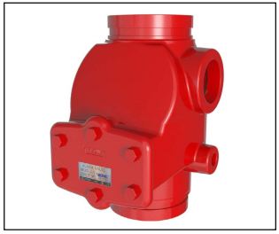
Alarm Check Valve J-1
IPV
Description
The Viking Model J-1 Alarm Check Valve serves as a check valve by trapping pressurized water above the clapper and preventing reverse flow from sprinkler piping.
The valve is designed to initiate an alarm during a sustained flow of water (such as the flow required by an open sprinkler) by operating an optional water motor alarm and/or alarm pressure switch. The valve is made suitable for use on variable pressure water supplies by adding the optional retard chamber to the standard trim.
Features
- Ductile iron body for less weight and extra strength.
- Rubber-faced clapper hinged to access cover for quick removal and easy servicing.
- All moving parts can be serviced without removing the valve from the installed position.
- With the cover/clapper assembly removed, clapper rubber replacement requires removal of only one screw.
- External by-pass trim to minimize clapper movement and false alarm.
- Trim allows installation of optional non-interruptible pressure switch to activate an electric alarm panel and/or remote alarm.
- Can be installed on constant or variable pressure water supplies.
- Can be installed vertically or horizontally, with the access cover facing up.
- Valve housing tapped for inlet and outlet pressure gauges, alarm devices, and system main drain.
- Trim includes alarm test valve for testing alarms without reducing system pressure.
Listings and Approvals
cULus Listed: Guide VPLX - 300 psi (20.7 bar) MWP
FM Approved: Waterflow Alarm Valves - 300 psi (20.7 bar) MWP
American Bureau of Shipping (ABS): Certificate No. 03-HS405911A/1-PDA
NYC Department of Buildings: MEA 89-92-E Vol. XI - 250 psi (17.2 bar) MWP
LPCB: 300 psi (20.7 bar) MWP
VdS: DN80 - G 4960086, DN100 - G 4960087, DN150 - G 4960088, DN200 - G 4960089 - 250 psi (17.2 bar) MWP
CE Certified: Standard EN-12259-2, EC-certificate of conformity 0832-CPD-2010 - 250 psi (17.2 bar) MWP
TECHNICAL DATA
Specifications
Friction Loss - Refer to Table 1 Pressure Rating - 300 psi (20.7 bar) water working pressure. Factory tested hydrostatically to 600 psi (41.4 bar). The valve may be hydrostatically tested at 350 psi (24.1 bar) and/or 50 psi (3.4 bar) above the normal water working pressure, for limited periods of time (two hours), for the purpose of acceptance by the AHJ. If air testing is required, DO NOT exceed 40 psi (2.8 bar) air pressure.
Material Standards Refer to Table 1.
Ordering Information
The valve is listed and/or approved with specific trim for use up to 300 psi (20.7 bar). No substitutions or omissions, in part or in full, are allowed. Additional accessories to the standard trim packages are required for a complete system meeting the requirements of the applicable rules and codes. See appropriate technical data for additional information.
Part Numbers - Refer to Table 1.
Accessories -
a. Retard Chamber: Required when the Model J-1 Alarm Check Valve is installed on systems with a variable pressure water
supply to minimize unwanted (false) alarms.
b. Water Motor Alarm: The J-1 Alarm Check Valve is designed to operate a mechanical alarm during a sustained flow of water
(such as the flow required by an open sprinkler). Refer to the water motor alarm technical data.
c. Alarm Pressure Switch: The J-1 Alarm Check Valve trim allows installation of pressure switches to operate local electric alarms
and/or remote electric alarms during a sustained flow of water (such as the flow required by an open sprinkler).
Additional accessories are available and may be required for operation or supervision. Refer to the system description for complete operating trim requirements.
Trim Packages -
Viking 300 psi (20.7 bar) trim is required to maintain cULus Listings and FM Approvals. Trim packages include all
necessary nipples, fittings, standard trim accessories and necessary gauges.
a. 300 psi (20.7 bar) vertical trim* for use when the J-1 Alarm Check Valve is installed vertically.
b. 300 psi (20.7 bar) horizontal trim* for use when the J-1 Alarm Check Valve is installed horizontally
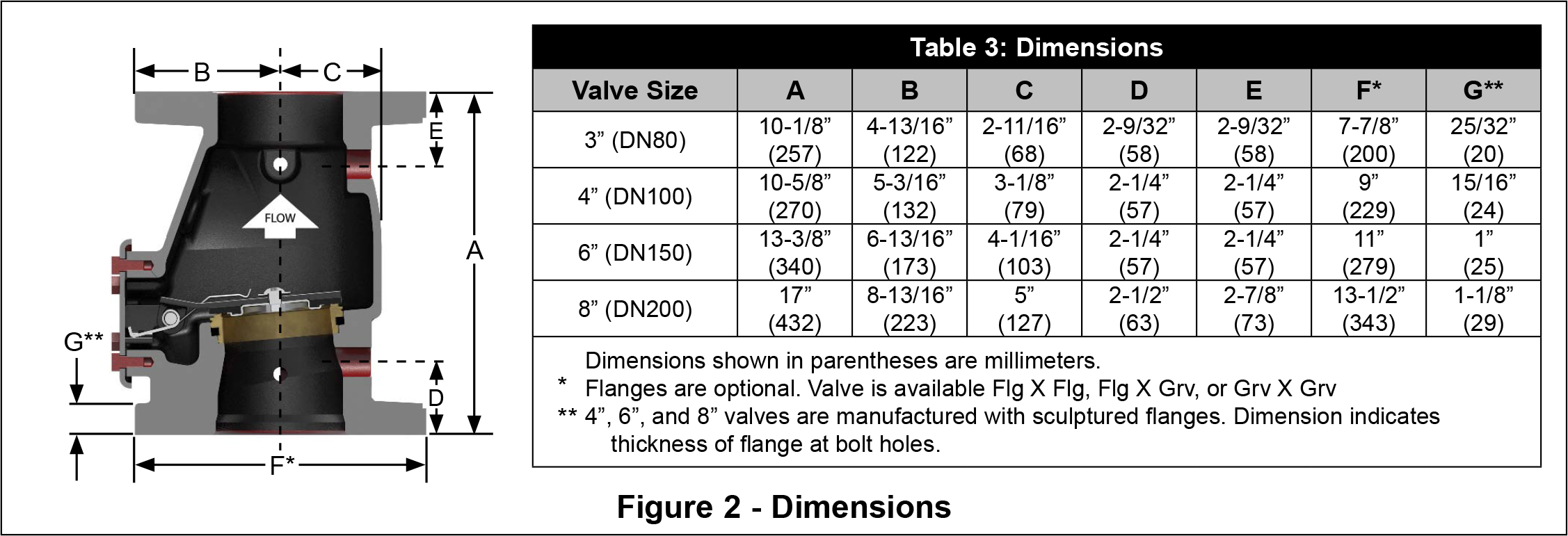
Table 1: Model J-1 Alarm Valve Technical Data
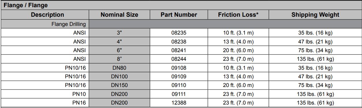
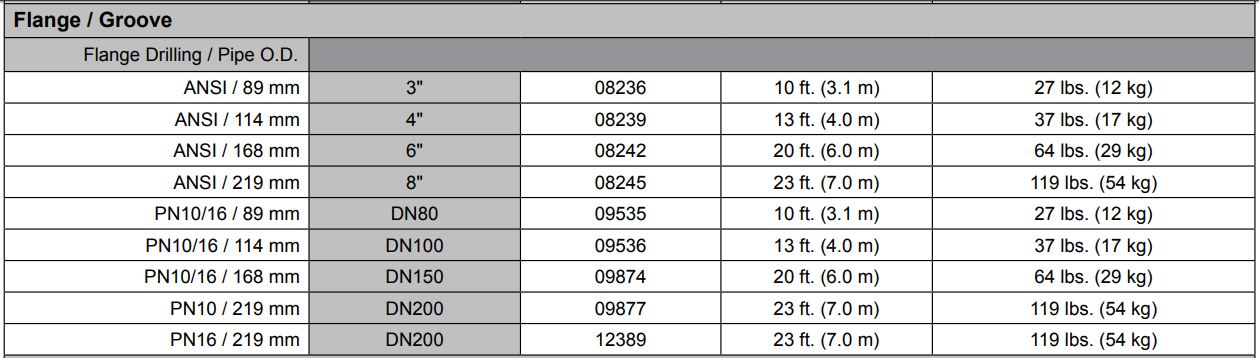
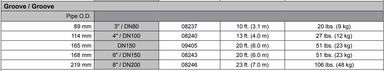
* Expressed in equivalent length of Schedule 40 pipe based on Hazen & Williams formula: C = 120.
NOTE: Systems with water working pressures above 175 psi (12.1 bar) may require extra-heavy pattern fittings. Model J-1 Alarm Valve flanges
are Ductile Iron ANSI B16.42 Class 150 with a maximum water working pressure of 300 psi (20.7 bar). ANSI B16.42 Class 150 flanges are NOT
compatible with ANSI Class 250 or Class 300 flanges. To mate the Model J-1 Alarm Check Valve with ANSI Class 250 or Class 300 flanges, use
the grooved-inlet/grooved-outlet style installed with listed grooved/flanged adapters of the appropriate pressure rating. For piping with grooved
connections, the grooved-inlet and/or grooved-outlet Model J-1 Alarm Check Valve may be installed with listed grooved couplings of the appropriate
pressure rating.
INSTALLATION
The Model J-1 Alarm Check Valve must be installed in an area not subject to freezing temperatures or physical damage. When corrosive atmospheres and/or contaminated water supplies are present, it is the owner’s responsibility to verify compatibility with the Model J-1 Alarm Check Valve, trim, and associated equipment. Prior to installing the valve, thoroughly flush the water supply piping to verify that no foreign matter is present. The Model J-1 Alarm Check Valve may be installed in the vertical position with direction of flow up, or in the horizontal position with the access cover up.
- Verify that the appropriate trim chart and technical data for the Alarm Check Valve and associated equipment are available.
- Remove all plastic thread protectors from the openings of the Alarm Check Valve.
- Apply a small amount of pipe-joint compound or tape to the external threads of all pipe connections required. Take care not to allow any compound, tape, or other foreign matter inside any nipples or openings of the valve or trim components.
- Install the Model J-1 Alarm Check Valve and trim according to current Viking Trim Charts for the valve used. Trim charts are provided with trim package and can be found on the Viking website.
- Verify that all system components are rated for the water working pressure of the system.
Placing the System in Service
When the wet-pipe system is ready to be placed in service, verify that all equipment is adequately heated and protected to prevent freezing and physical damage.
Note: For proper operation of the wet system and to minimize unwanted (false) alarms, it is important to remove trapped air from the system when filling it with water. Air trapped in the system may also cause intermittent operation of the water motor alarm during a sustained flow of water (such as the flow required by an open sprinkler or the system test valve). Consider installation of auxiliary vents to facilitate venting.CAUTION
Opening of the water supply main contorl valve will result in water flow from any openings in the system.
1. Verify that auxiliary drains are closed and that the system is free of leaks.
2. Open the system test valve (and any auxiliary vents provided to facilitate removal of air from the system) to allow air to escape
from the system while it is filling with water.
3. If desired, close the alarm shut-off valve to prevent local alarms from operating while filling the system.
Note: Alarms and electric panels controlled by an alarm pressure switch installed in the “electric
alarm panel” connection provided in the trim cannot be interrupted. (See trim chart.)
4. Slowly open the water supply main control valve.
5. Allow the system to completely fill with water. Allow water to flow from the system test valve, and any other open vents provided,
until all air is exhausted from the system.
6. After all air is exhausted from the system, close the system test valve and all other open vents.
7. The pressure gauge on the system side of the Alarm Check Valve Clapper should indicate water pressure equal to or greater than
the water pressure indicated on the gauge located on the supply side of the clapper.
8. OPEN the Alarm Shut-Off Valve in the Alarm Valve trim, and verify that all other valves are in their normal operating position.
9. Secure all valves in their normal operating position.
10. Notify the Authority Having Jurisdiction, remote station alarm monitors, and those in the affected area that the system is in service.
OPERATION
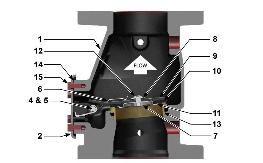
(Refer to Figures 1 & 2)The Model J-1 Alarm Check Valve is manufactured with a hinged clapper (9) equipped with a torsion spring (6) to assure proper operation when the valve is installed in the horizontal position.
Minor flows, resulting from small surges, travel around the clapper through external by-pass trim to minimize false alarms. Rubber
gasket (10) forms a tight seal against brass water seat (13). This seal, and the check valve installed in the external by-pass trim, serve
to trap higher pressurized water in the sprinkler piping and prevent reverse flow.
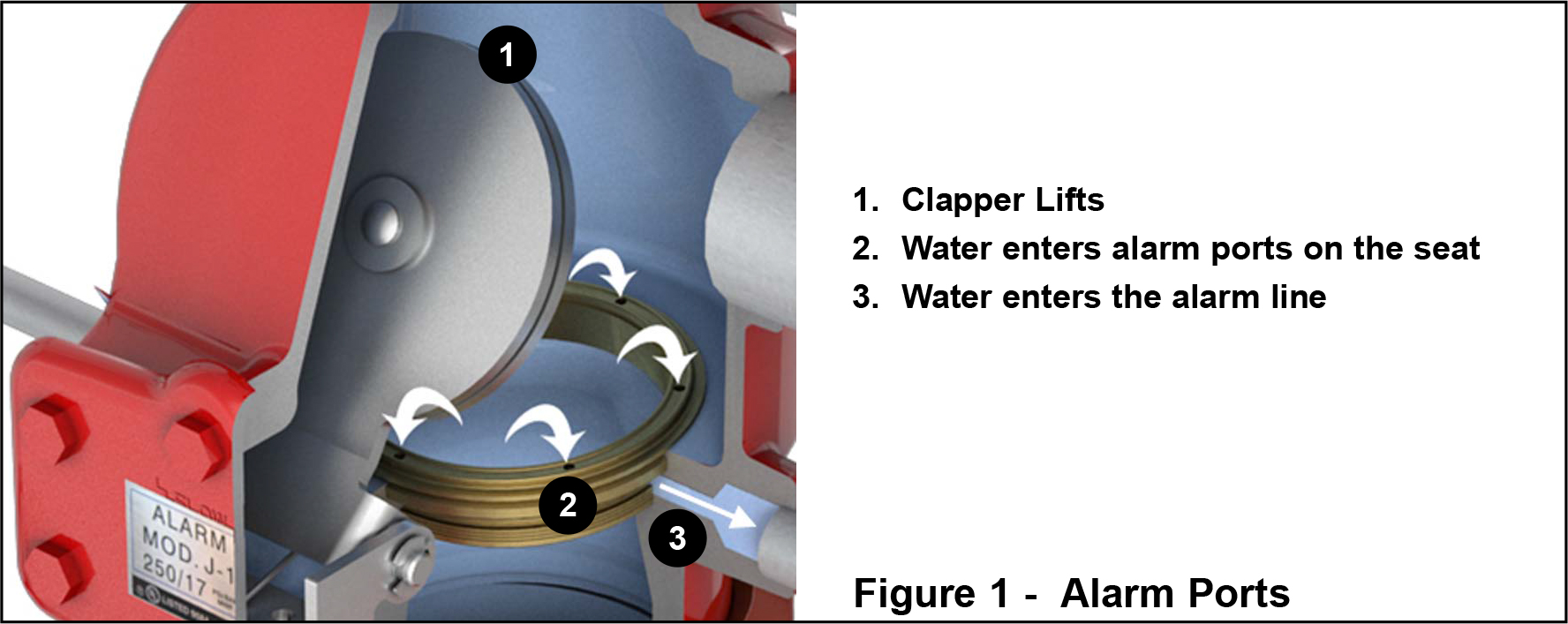
During a sustained flow of water, such as the flow required by an open sprinkler, hinged clapper (9) moves off seat (13) to the open position. Water flows through ports in grooved seat (13), and enters the alarm port to activate alarm devices connected to the system.
Operation with Retard Chamber:
When the optional retarding chamber is used, water entering the grooved seat alarm port is directed into the retarding chamber. Temporary pressure surges or fluctuations, large enough to move the valve clapper, are automatically drained through the restricted drain.
During a sustained flow of water, such as the flow required by an open sprinkler, the clapper will be held off its seat. The retarding
chamber will fill faster than water can drain through the restricted drain of the alarm valve trim. Alarm devices will be pressurized. Refer
to technical data describing the Viking Retarding Chamber and alarm devices.
NOTICE
The owner is responsible for maintaining the fire protection system and devices in proper operating condition. For minimum maintenance and inspection requirements, refer to recognized standards such as those produced by NFPA, LPC, and VdS which describe care and maintenance of sprinkler systems. In addition, the Authority Having Jurisdiction (AHJ) may have additional maintenance, testing and inspection requirements which must be followed.
WARNING
Any system maintenance or testing that involves placing a control valve or detection system out of service may eliminate the fire protection of that system. Prior to proceeding, notify all Authorities Having Jurisdiction. Consideration should be given to employment of a fire patrol in the affected area.
It is imperative that the system be inspected and tested on a regular basis. The frequency of the inspections may vary due to contaminated water supplies, corrosive water supplies, and corrosive atmospheres. For minimum maintenance and inspection requirements, refer to NFPA 25. In addition, the Authority Having Jurisdiction may have additional maintenance, testing, and inspection requirements that must be followed.
Monthly visual external inspection of Alarm Check Valves is recommended.
1. Verify that pressure gauges indicate normal water supply pressures. It is normal for the gauge on the system side of the clapper
to register a higher pressure than the gauge on the supply side of the clapper because pressure surges are trapped above the
clapper.
2. Check for signs of mechanical damage and/or corrosive activity. If detected, perform maintenance as required or, if necessary,
replace the device.
3. Verify that valve and trim are adequately heated and protected from freezing and physical damage.
4. When equipped with variable pressure trim, verify that there is no unwanted leakage from the restricted drain of the retard chamber. It is normal for drainage to occur during pressure surges that exceed the capacity allowed through the by-pass trim.
5. Verify that the water supply main control valve is open, and that all valves are in their normal operating position and appropriately
secured.
QUARTERLY TESTS
Water Flow Alarm Test
Quarterly testing of water flow alarms is recommended and may be required by the Authority Having Jurisdiction and NFPA 25.
1. Notify the Authority Having Jurisdiction, remote station alarm monitors, and those in the area affected by the test.
Note: An alarm shut-off valve is provided to silence local alarms. No shut-off valve is provided
for the pressure switch connection intended to activate electric alarm panels. (Refer to J-1 Alarm
Check Valve Trim Chart.)
2. To test electric alarms (if provided) and/or mechanical water motor gong (if provided), OPEN the system test valve. If freezing
weather or other conditions prohibit use of the system test valve, OPEN the alarm test valve in the alarm check valve trim.
Note: Use of the alarm test valve allows testing of alarms without reducing the system pressure.
a. Electric alarm pressure switches should activate.
b. Electric local alarms should be audible.
c. The local water motor alarm should be audible.
Note: When using the system test valve for the water flow alarm test, intermittent operation of the
water motor alarm may indicate air is trapped in the system (refer to the PLACING THE SYSTEM IN SERVICE paragraph of section 4).
d. Verify that remote station alarm signals (if provided) were received.
3. When testing is complete, close the test valve used.
4. Verify:
a. All local alarms stop sounding and electric panels (if provided) reset.
b. All remote station alarms reset.
c. Retard chamber and water motor alarm supply piping has drained properly.
5. Verify that the alarm shut-off valve in the Alarm Check Valve trim is OPEN, the alarm test valve is CLOSED, and all valves are in
their normal operating position and appropriately secured.
6. Notify the Authority Having Jurisdiction, remote station alarm monitors, and those in the affected area that testing is complete.
Main Drain Test
Semi Annual performance of the Main Drain Test is recommended and may be required by the authority having jurisdiction to verify
integrity of the water supply.
1. Notify the authority having jurisdiction, remote station alarm monitors, and those in the area affected by the test.
2. Perform monthly visual inspection.
3. Verify that adequate drainage is provided for full flow from Main Drain outlet.
4. Record pressure reading from the water supply pressure gauge.
5. Fully OPEN the main drain located on the Alarm Check Valve.
6. When a full flow is developed from the main drain, record the residual pressure from the water supply pressure gauge.
7. When the test is complete, SLOWLY CLOSE the main drain.
8. Compare test results with previous flow information. If deterioration of the water supply is detected, take appropriate steps to
restore adequate water supply.
9. Verify that normal water supply pressure has been restored, and that all alarm devices and valves are secured in normal operating position.
10. Notify the Authority Having Jurisdiction, remote station alarm monitors, and those in the area affected by the test that the test is
complete. Record and/or provide notification of test results as required by the Authority Having Jurisdiction.
Five-Year Internal Inspection
(Refer to Figure 3)
Internal inspection of Alarm Check Valves is recommended every five years unless inspections and tests indicate more frequent internal inspections are required.
1. Notify the Authority Having Jurisdiction, remote station alarm monitors, and those in the area affected that the system will be taken
out of service. Consideration should be given to employment of a fire patrol in the affected areas.
2. Close the water supply Main Control Valve, placing the system out of service.
3. Open the main drain. If necessary, open the system test valve to vent and completely drain the system.
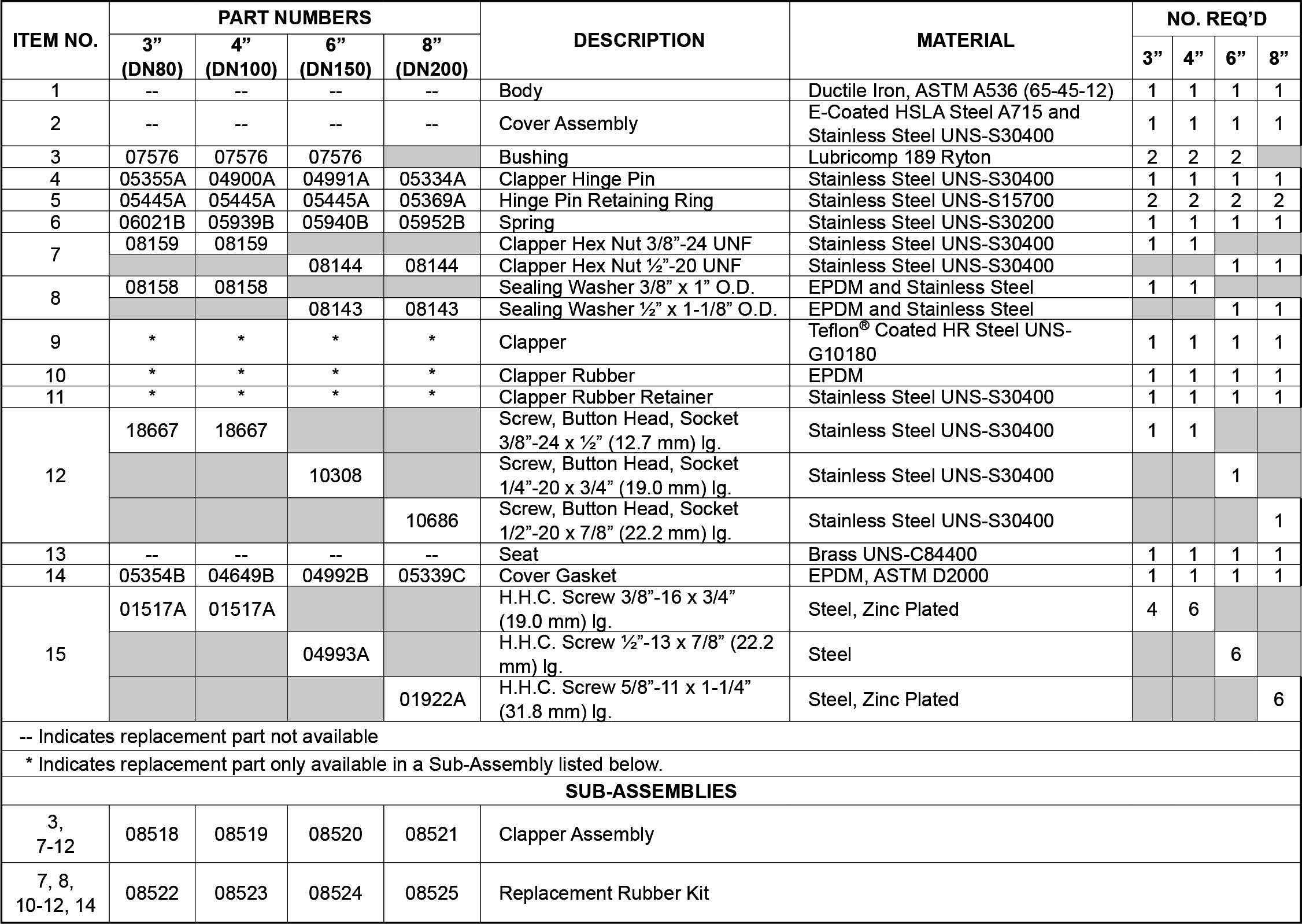
4. Use appropriate wrench to loosen and remove cover screws (15), and remove Cover/Clapper assembly (2-12).
5. Inspect water seat (13). Wipe away all contaminants, dirt, and mineral deposits. Clean any orifices in the seat that are restricted
or plugged by mineral deposits. DO NOT use solvents or abrasives.
6. Inspect cover/clapper assembly (2-12) and cover gasket (14). Test hinged clapper (9) for freedom of movement and spring (6) for
tension retention. Spring (6) tension should engage when the top of hinged clapper (9) is moved from perpendicular to cover (2)
toward the open (flow) position. Renew or replace damaged or worn parts as required.
CAUTION
Never apply any lubricant to seats, gaskets, or any internal operating parts of the valve. Petroleum-based grease or oil will damage rubber components and may prevent proper operation.
7. When internal inspection of the alarm check valve is complete, perform step 6 of the Maintenance paragraph in section 5 to reinstall Cover/Clapper Assembly (2-12).
8. Place the wet system back in service, Refer to the Placing the System in Service paragraph in section 4.
Maintenance (Refer to Figure 3)
1. Perform steps 1 through 6 of the Five Year Internal Inspection paragraph in Section 6.
2. To remove clapper rubber (10):
a. Use the appropriate wrench to loosen and remove the button-head socket screw (12), hex nut (7), sealing washer (8), and
rubber retainer (11).
b. Remove the clapper rubber (10) for inspection. If the clapper rubber shows signs of wear such as cracking, cuts, or excessively deep grooves where the rubber contacts the water seat, replace the rubber.
3. To re-install clapper rubber (10):
a. Place clapper rubber (10) over the center hub of the rubber retainer (11).
b. Position the retainer (11) (with rubber in place) against clapper (9) as shown in Figure 3.
c. Replace and tighten the button-head socket screw (12), sealing washer (8), and hex nut (7), as shown in Figure 3. DO NOT
over-tighten.
4. To remove the clapper (9), spring (6), and/or hinge pin (4), remove hinge pin retaining rings (5), to free the hinge pin (4) for removal. After the hinge pin (4) is removed, the clapper (9) and spring (6) can be removed.
5. To re-install the clapper (9), spring (6), and/or hinge pin (4):
a. Verify that the clapper rubber (10) is in good condition and that it is properly installed.
b. Position the clapper (9) with the elongated hinge holes aligned between the holes of the hinge bracket welded inside the cover
(2). The system (top) side of the clapper (9) must face the direction indicated by the flow arrow stamped inside the cover (2).
c. Insert the hinge pin (4) through the holes at one end of the hinge assembly. Before continuing, re-install the spring (6), using
care to orient the spring as shown in Figure 3. Continue to push the hinge pin (4) through the holes at the remaining end of
the hinge assembly.
d. Re-install the hinge pin retaining rings (5).
6. To re-install cover/clapper assembly (2-12):
a. Verify that the cover gasket (14) is in position and that it is in good condition.
b. Slide the cover/clapper assembly (2-12) into the Alarm Valve so that the clapper rubber (10) contacts the grooved water
seat (13).
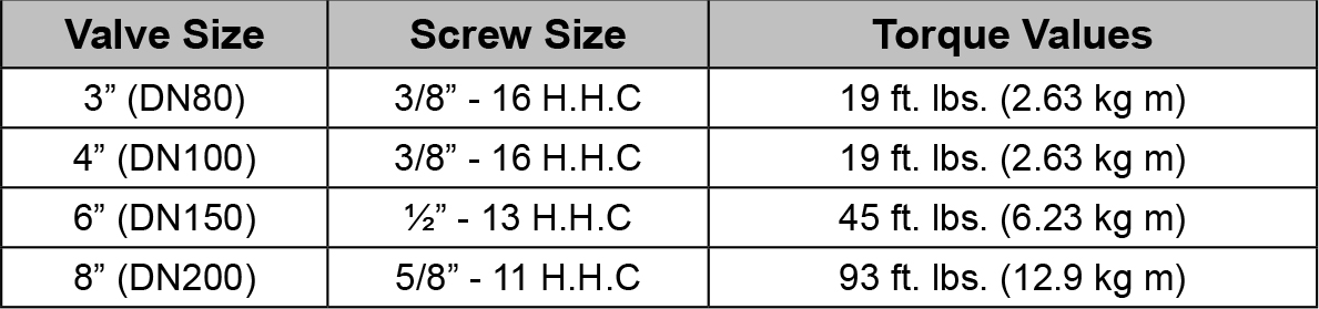
c. Replace cover screws (15). Use the appropriate wrench to evenly cross-tighten all screws to the torque values listed in
Table 2 for the valve used. DO NOT over-tighten.
Table 2: Torque Values for Model J-1 Alarm Valve Cover Screws
7. To place the wet system back in service, refer to the Placing the System in Service paragraph in section 4.
AVAILABILITY
The Viking J-1 Alarm Check Valve is available through a network of domestic and international distributors. See the Viking Corporation Web site for closest distributor or contact The Viking Corporation.
GUARANTEES
For details of warranty, refer to Viking’s current list price schedule or contact Viking directly.