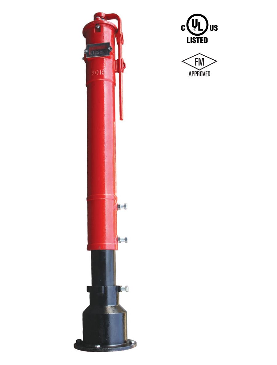
Vertical Indicator Post
IPV
IPV - Vertical Indicator Post
Physical Data
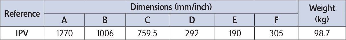
IPV - Vertical Indicator Post
Trench Depth
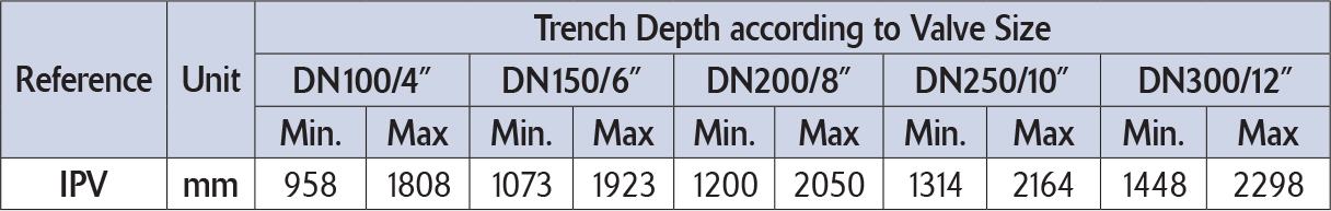
IPV - Vertical Indicator Post
Specifications
- Indicator of "Open" and "Shut" positions
- Used to operate a buried or hidden post indicator valve
- 850 mm adjustment range
- Wrench handle fits over a "U" bracket on the barrel, this can be fixed with a padlock to secure the operating wrench to the barrel
- Internally and externally coated in red epoxy RAL3000
- 2.2 m long stem bar is supplied (for valves of 4” or more)
IPV
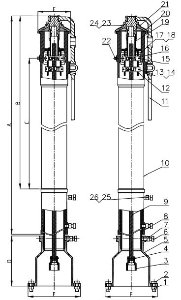
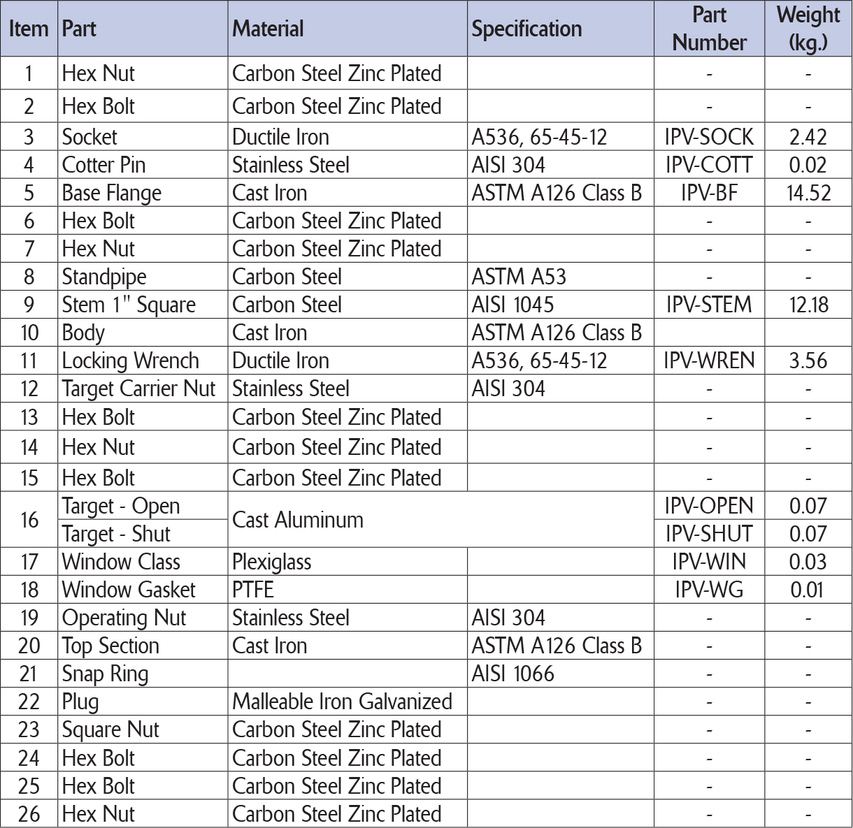
Materials List
Installation
1.) Disassemble the Indicator Post
Take off the Locking Wrench (11), loosen the two Hex bolt (24) and Square Nut (23) and remove the Top Section (20), operating nut assembly and the Square Stem (9) as well as the socket (3). Slide off the Body (10) from the Standpipe (8) by loosening the two Hex Bolts (6) and Hex Nuts (7), slide off the Standpipe (8) from the Base Flange (5).
2.) Install the Base Flange and Lower Standpipe
Attach the Base Flange (5) together with the Standpipe (8) to the Post Flange of the post indicator valve using the four Hex nuts (1) and Hex bolts (2). Fix the Standpipe (8) to the Base Flange (5) using the Hex Bolt (6) and Hex Nut (7).
3.) Adjust the Ground Line Mark
Pull the Body (10) over the Standpipe (8) until the Ground Line Mark on the Body (10) is the same height as the ground level. Tighten the two Hex Nuts (6) and Hex Bolts (7).
4.) Adjust the Square Stem
Lower the Stem (9) into the Body (10) such that the socket (3) fits over the operating nut of the post indicator valve. Ensure that Stem (9) engages the Operating Nut (19) a minimum of 2” but no more than 4.5”. To check for correct engagement, the end of stem should be 2 to 4 inches below the top of the Body (10).
5.) Adjust the Targets
Lower the Stem (9) into the Body (10) such that the socket (3) fits over the operating nut of the post indicator valve.
Ensure that Stem (9) engages the Operating Nut (19) a minimum of 2” but no more than 4.5”. To check for correct engagement, the end of stem should be 2 to 4 inches below the top of the Body (10).
5.) Adjust the Targets
Remove the Target Carrier Assembly (12, 13 & 14) from inside the Body (10) by rotating the Operating Nut (19) counter-clockwise. The “Open” Target (16) and “Shut” Target (16) are adjusted up and down on the Target Carrier Assembly (12, 13 & 14) by pulling the middle section of the Target (Open & Shut) a small distance away from the Target Carrier Assembly (12, 13 & 14) and sliding the Target (Open & Shut) up or down as desired.
- If the post indicator valve is opened by turning the handwheel counter clockwise: Move the two Open Targets (16) to the very top of the Target Carrier Assembly. Locate the two “Shut” Targets according to the size of the post indicator valve size (stem) turning distance.
- If the post indicator valve is opened by turning the handwheel clockwise: Move the two “Shut” Targets to the very top of the Target Carrier Assembly (12, 13 & 14). Locate the two “Open” Targets (16) according to the size of the post indicator valve (stem) turning distance.
6.) Final Assembly and Test
Insert the Target Carrier Assembly (12, 13 & 14) back into the Top Section (20) by rotating the Operating Nut (19) clockwise. Rotate the Operating Nut (19) until the “Open” Target (16) is centered in the window of the Body (10). Lower the Top Section (20) with the Target Carrier Assembly (12, 13 & 14) onto the Body (10), carefully ensuring that the Stem (9) engages with the Operating Nut (19) at least 50mm (2 in) but not more than 120mm (4.5 in). Secure the Top Section (20) to the Body (10) by tightening the hex bolt (24) and Square Nut (23). Close the post indicator valve and check to make sure that the “Shut” Target is properly centered in the window of the Body (10) and adjust as necessary.
Maintenance
Lubrication
Oil the bearing in the Top Section (20) at least once a year by adding several drops of oil in the hole located on the top of the Operating Nut (19).